Atmega8 Datasheet Na Russkom

My Arduino Uno has a ATMEGA328P-PU microcontroller, and bunch of other stuff on the board. I'd like to program the chip without the Arduino software, and only the minimum of other components. I want to eventually create things without the cost of Arduino, and I want to learn about the other parts on the board and add them back as as needed. I'm comfortable with C and gcc, so I can probably figure out the software part. But what, if anything, besides these two products below, do I need to have in the breadboard with the microcontroller? $ begingroup $ @capcom First google result for 'site:atmel.com atmega typical application' finds.
Not only does this application note have a minimal circuit to get the MCU to work, it goes in to great detail on how to connect a programming port, select oscillators, deal with ESD hazards, potential glitches on the reset line, connecting JTAG, PCB layout, and basically everything a beginner needs. Finding this information is the most useful skill a beginner can have. $ endgroup $ – Jan 15 '13 at 3:38 •. $ begingroup $ OK, I'll rehprase.
Rob, you should know that any manufacturer of a non-trivial device will publish documentation to answer exactly this question. The manufacturers have a clear interest in making it easy for you to use their product. Skimming the datasheet is the way to start. For complex things like microcontrollers, there might be a separate application note. 'typical application' are the magic words you need to use in your search terms. It's not that it's bad to ask for help, but it's good to know how to fish.
$ endgroup $ – Jan 15 '13 at 16:28. All you need apart from the programmer and the chip is a couple of decoupling caps, and some way of connecting the programming signals to the breadboard. So: • 1 largish electrolytic cap (e.g. >100uF) You can maybe do without this if your source is nice and quiet (e.g. 
Battery) • 1 100nF ceramic across the power pins of the micro • 1 10kΩ resistor to connect from the reset pin to Vcc to hold the micro out of reset. • Some jumper wire to connect up nodes on your breadboard (you can buy ready made jumper wires, but I use a 22AWG roll and cut my own - much cheaper if you do this a lot) • A header to plug your programmer cable into. According to the it looks like you need a 2x3 pin 2.54mm pitch header.
High-performance, Low-power Atmel®AVR® 8-bit Microcontroller. Typical values contained in this datasheet are based on simulations and characterization of. Brittany 21.09.16 17:21 comment2, skachat_igru_novyi_chelovek_pauk_na_android_s_avtozagruzkoi_kesha, 583.
The programmer you have programs the ATmega8 through the ISP interface on the device. Here is the pinout of your programmer: You can see the circles and the one square? The square denotes the 1st pin, or MOSI.
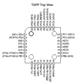
I think I found the right datasheet to your ATmega8 MCU, please double check the datasheet for the MCU that you have. Extracted from the ATmega8/ATmega8L datasheet found here: You can see that pin 19 (PB5) is the SCK pin. Pin 18 is MISO, 17 is MOSI, 1 is RESET. These are the pins that connect to the appropriate ISP pins that you can see in the first picture above.  So your overall system will be like this: • Have the ATmega8 powered from a reliable DC 5V power source • Ensure the ATmega8 is grounded • Connect the pins of the ISP programmer to the appropriate pins on the ATmega8 • Pull up resistor (~10k) on the RESET pin. This is all you should need to get the programmer to talk to your MCU using your computer.